How to Diagnose Communication Issues with the ECU?
Tools

I. Preliminary Check. Check for Communication Related U-Codes in Other ECUs.
- Let’s say your scanner has no communication with the ABS Module (Anti-lock Braking System).
- Before you start checking the wiring, try to scan the whole car and see if there are no communication codes stored in other ECUs.
- It’s not a rule, but frequently (on modern cars) if your scanner has no communication with one ECU, other ECUs will store a corresponding U-xxxx code indicating that they also cannot communicate with that offending module.
- For example, when the ECM/PCM doesn’t communicate with the ABS Module, it might store the following code:
- U0121 Lost Communication with ABS Module.
- If there are U-codes
- Continue with the wiring troubleshooting.
- U-codes verify that there is indeed a communication problem.
- If there are no U-codes
- Try a different scan tool, if possible. It can save you a lot of unnecessary diagnostics time.
- This would verify that ‘no communication’ is not a scan tool software/hardware related issue.
- Keep in mind that frequently other ECUs will not store any communication related U-codes even though one or more ECUs might be disconnected from the network.
- So use this test as a corroborating evidence, but don’t fully rely on it if there are no U-codes.
- Try a different scan tool, if possible. It can save you a lot of unnecessary diagnostics time.
II. Wiring Troubleshooting
- Obtain a detailed wiring diagram for the offending module.
- While all wiring diagrams for the various car models and modules will look different, all ECUs have certain common inputs (and sometimes outputs) that are essential for proper communication.
- It might be that out of 100s of wires, you only need to focus on 4. Some small ECUs/sensors can operate with as few as 2 wires.
- To give you an idea, let’s take a typical ECM. Here is an oversimplified example of the wiring that you might need to check, before you would condemn the ECM as faulty:
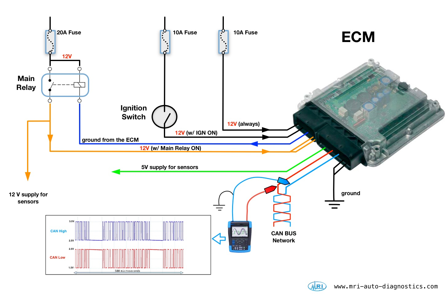
1. Power
- All ECUs have at least one wire that supplies 12V Battery Power to it.
- It could be a constant 12V Battery Power (B+), and/or 12V Ignition Switch Power that is powered with ignition switch ON (IGN).
- Refer to the corresponding wiring diagram and test all the power inputs at the ECU’s connector.
- …
- Some ECUs (like ECM, BCM, etc.) might have additional power inputs.
- ECM usually has the Main Relay (aka EFI Relay, DME Relay, etc.) which supplies 12V to all kinds of sensors/actuators/solenoids and also (frequently but not always) to the ECM itself.
- Usually ECM is the one that energizes (grounds) the Main Relay, and when it’s energized, ECM receives an additional 12V from it.
- Without this 12V from the Main Relay in a lot of cases ECM will not be awake, and will not communicate with the scanner.
- Check if the ECM energizes the Main Relay (provides a good ground). Do this only when all the other power supplies are on.
- If the Main Relay is not being activated by the ECM, there is a very slight chance that 5V sensor supply line is shorted to ground (directly or through one of the sensors). Finding that kind of short might involve a lot of work, disconnecting all the sensors that are supplied by that 5V and tracing wires for shorts, corrosion.
- Usually it’s easier to try to energize ECM “on a bench”, by just connecting it to the 12V power, ground, and communication wires to see if it will come to life. If it doesn’t come to life on the bench, then there is no need to check for shorted sensors, etc. Simply replace the ECM.
-
📝 No Start | Shorted Vehicle Speed Sensor | 2002 Acura.
- The car has died twice when engaged in reverse, then wouldn’t restart. When the Transmission Control Module (TCM) was disconnected, car started right up.
- Turned out the car had a shorted Vehicle Speed Sensor (VSS), that was apparently shorting the circuitry inside the TCM, which went ‘offline’, in turn pulling other modules ‘offline’, resulting in a no-start.
- Note, all the power wires have to be tested under load (e.g. using a light bulb).
2. Ground
- Note, all the ground wires have to be tested under load.
- 📝 If the car starts with the OBDII scanner plugged in, but doesn’t start with the scanner unplugged (PCM relays might be clicking), check the ECM ground.
3. Communication wires
- Usually, car ECUs are all interconnected with just 1 or 2 wires (and sometimes fiber optics network).
- Most modern vehicles usually utilize protocols like CAN Bus Protocol (2 wires), K-Line Protocol (1 wire), LIN Bus Protocol (1 wire), MOST (fiber optics), etc., for communication between computers and with the diagnostic scanner.
- If one of the communication wires is shorted to ground/power/together, the whole network might go offline. That means, your scanner will not be able to communicate with any of the ECUs on that network. This can also happen when one of the ECUs on the network is shorting the communication line internally, say after water damage.
- For more information on the protocol-specific troubleshooting tips, read below.
3a. CAN Bus

- CAN Bus in cars is standardized in ISO 11898-2 (more details in here)
- All CAN Bus pair wires are twisted together (CAN H and CAN L).
- The twisted pair wire is an essential part of how the differential mode filtering works on a CAN Bus, and without it the signal can be easily distorted.
-
Terminating Resistors
- As you can see on the picture above, CAN Bus wires are usually connected by the two terminating resistors (in parallel) somewhere on the network, each separately measuring 120Ω.
- When they are both connected to the network, resistance between CAN Bus wires becomes 60Ω (link).
- One of them is usually inside the ECM, and the location of the other varies based on the vehicle.
- Without them there will be a lot of noise on the CAN Bus.
- If the ECU with the terminating resistor is disconnected, resistance between CAN Bus wires will become 120Ω.
- If resistance is more than 120Ω, it means that there is a problem with CAN Bus wires and/ or possibly with both ECUs that host terminating resistors.
- As you can see on the picture above, CAN Bus wires are usually connected by the two terminating resistors (in parallel) somewhere on the network, each separately measuring 120Ω.
-
Resistance Test
- A simple and a quick CAN Bus check can be done with an ohmmeter.
- Turn ignition OFF, and measure resistance between terminals 6 and 14 of the OBDII connector.
- If the ohmmeter shows 60Ω, then you can move on to the next test. CAN Bus termination test passed.
- If it shows 120Ω, then there is an issue with the circuit for one of the terminating resistors (could be the wiring or the ECU hosting the terminating resistor).
- Turn ignition OFF, and measure resistance between terminals 6 and 14 of the OBDII connector.
- If the ohmeter shows much more than 120Ω, suspect open CAN Bus wiring.
- A simple and a quick CAN Bus check can be done with an ohmmeter.

-
Differential voltages

- Testing differential voltages will require a good voltmeter with min-max function (e.g. Fluke 88V) or an oscilloscope (e.g. Pico 4424).
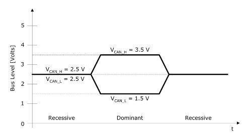
- CAN High usually (ISO 11898-2) ranges between 2.5V to 3.5V, and CAN Low between 1.5V to 2.5V.
- CAN Bus assigns
- logical ‘1’ to a typical differential voltage of 0V
- logical ‘0’ with a typical differential voltage of 2V
- The CAN Bus is in the dominant state (logical 1) if the differential voltage is greater than 0.9 V and in the recessive state (logical 0) if it is less than 0.5 V.
If you have any questions, please use a comment section below. 👇🏻

2011gmc 1500 no start no communication check the can bus and 60ohms next
My son has a merc it comes up no ecu has communications can anyone help
2005 no communication with ecu ?
No start montecralo/ just head lights and dash lights